Bringing nuclear safety to the next level
SAMOSAFER builds on the results of the SAMOFAR project
Bringing nuclear safety to the next level
World-wide research is being done on various classes of MSR each having its own characteristics. One major classification is the neutron spectrum. By adopting a moderator (mostly graphite) a thermal neutron spectrum can be obtained, while otherwise a fast or epithermal neutron spectrum results. The latter class of reactors can be subdivided into the ones using a fluoride fuel salt or a chloride fuel salt. Chlorides can contain a larger fraction of actinides and will therefore result in a harder neutron spectrum, making these better candidates for breeding with the uranium-plutonium fuel cycle, or for plutonium / minor actinide burning, while the fluoride salts perform better for breeding with the thorium fuel cycle.
Above mentioned reactor class has a single salt mixture acting both as a fuel and as a coolant. Alternatives exist as well, e.g. reactors with tubes filled with fuel salt surrounded by a coolant salt, like the MOLTEX design, or Fluoride-salt cooled High-temperature Reactors (FHR), sometimes also called Advanced High Temperature Reactors (AHTR) with a solid fuel design based on TRISO particles. Many of our results are transferable to these designs as well.
In the SAMOSAFER project we will develop new simulation models and tools and new safety barriers for the MSFR shown in Figure 1.1. The Primary Fuel Circuit (PFC) contains the reactor core (including the blanket, primary pumps, and heat exchangers) for power production, the Emergency Drain System (EDS) for safe storage of the fuel salt in accidental conditions, and the Fuel salt Treatment Unit (FTU) to continuously extract fission products from the fuel salt and to keep the Redox potential of the salt in the right range to reduce corrosion.

Figure 1.1: Schematic overview of the various systems in the MSFR
The challenge is to develop new assessment and simulation tools for Gen-IV reactors with respect to expected safety features. One of these safety features is the Emergency Draining System (EDS) shown in Figure 1.2. In case of overheating, loss of power, or other external events, the fuel salt flows via the Collector, Opening devices (among which freeze valves) and the Draining shaft into the Draining tank. Although the EDS is capable of keeping the fuel salt in a safe condition, each draining event is a massive transfer of hot fuel salt, which is not favoured. In this proposal we will investigate options to reduce the number of draining events through predictive reactor control, the design of a decay heat removal path from the reactor core via natural circulation, and by design of small normal operation drain tanks nearby the reactor core.

Figure 1.2: A detailed view of the Emergency Draining System (EDS) of the MSFR
During irradiation, several classes of elements (see Figure 1.3) build up in the fuel salt, each one requiring specific treatment. The yellow colored elements form fluorides and remain dissolved in the fuel salt during accidental conditions. The purple colored elements are the noble metals, which need to be extracted from the fuel salt before they will deposit in the cold parts of the primary circuit (e.g. in the heat exchanger). The default process for this is helium bubbling for which we will develop a simulation model validated with the EXPRESS facility. The size distribution of the noble metals is one of the results of the SALIENT irradiations in the HFR. In the proposal we will investigate the efficiency of a so-called “cold trap” to remove noble metals left over. The blue elements are the Gaseous Fission Products (GFP), which will escape from the fuel salt in the helium bubbling process as well. The state of niobium depends on the Redox potential of the salt. Iodine will react with the abundantly present cesium to form CsI, which will dissolve in the fuel salt up to concentrations of about 1% (mole).
For the removal of fission products and corrosion products in the fuel salt, and for make-up of fresh fuel, a small fraction of the fuel salt is continuously transferred to the FTU for processing. The processing scheme is schematically shown in Figure 1.4, indicating five major stages next to the helium bubbling process in the core:
In the project we will keep full track of the nuclides’ densities in the whole primary circuit including the reactor core and the FTU, and in the EDS during draining events.
The usual interpretation of severe accidents as applied to solid-fuel nuclear reactors is not directly transferable to the class of liquid-fuel reactors. To fully extend the concept of severe accident to the MSR, we will use a generalization of the definition as developed in the SAMOFAR project:
A severe accident in a nuclear reactor is an accident during which the nuclear fuel radionuclide confinement function is significantly degraded, regardless whether the fuel is inside the reactor, being handled or in a storage area.
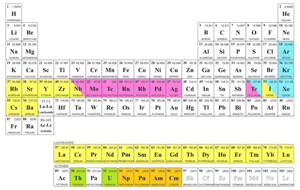
Figure 1.3: Overview of the elements formed in the fuel salt. Yellow elements remain dissolved in the fuel salt. The noble metals (purple) and gaseous fission products (blue) can be removed from the fuel salt via helium bubbling and/or fluorination
We aim to advance our safety barrier designs from TR level 2-3 to 4. Our simulation tools and barrier concepts like freeze valves, draining and storage systems, iodine trapping and off-gas systems, scaling laws for reactor design, and uncertainty quantification methods will be demonstrated to the MSFR, but will also be transferable to other MSR designs, as well as to other Gen-IV reactors and other industries. In our safety analyses we will focus on the reactor core, the FTU and the EDS, as these will be the major sources of radionuclides. We are confident this approach makes our results broadly applicable and the impact of our work as high as possible.